Feedback Linear Actuator 85151 Potentiometer
The Motion 85151 Linear Actuator for operating loads up to 500 lbs.
In some applications it is necessary to provide a simple and reliable way to measure the actuator’s position.
| Potentiometer Wiring | MOTOR Wiring |
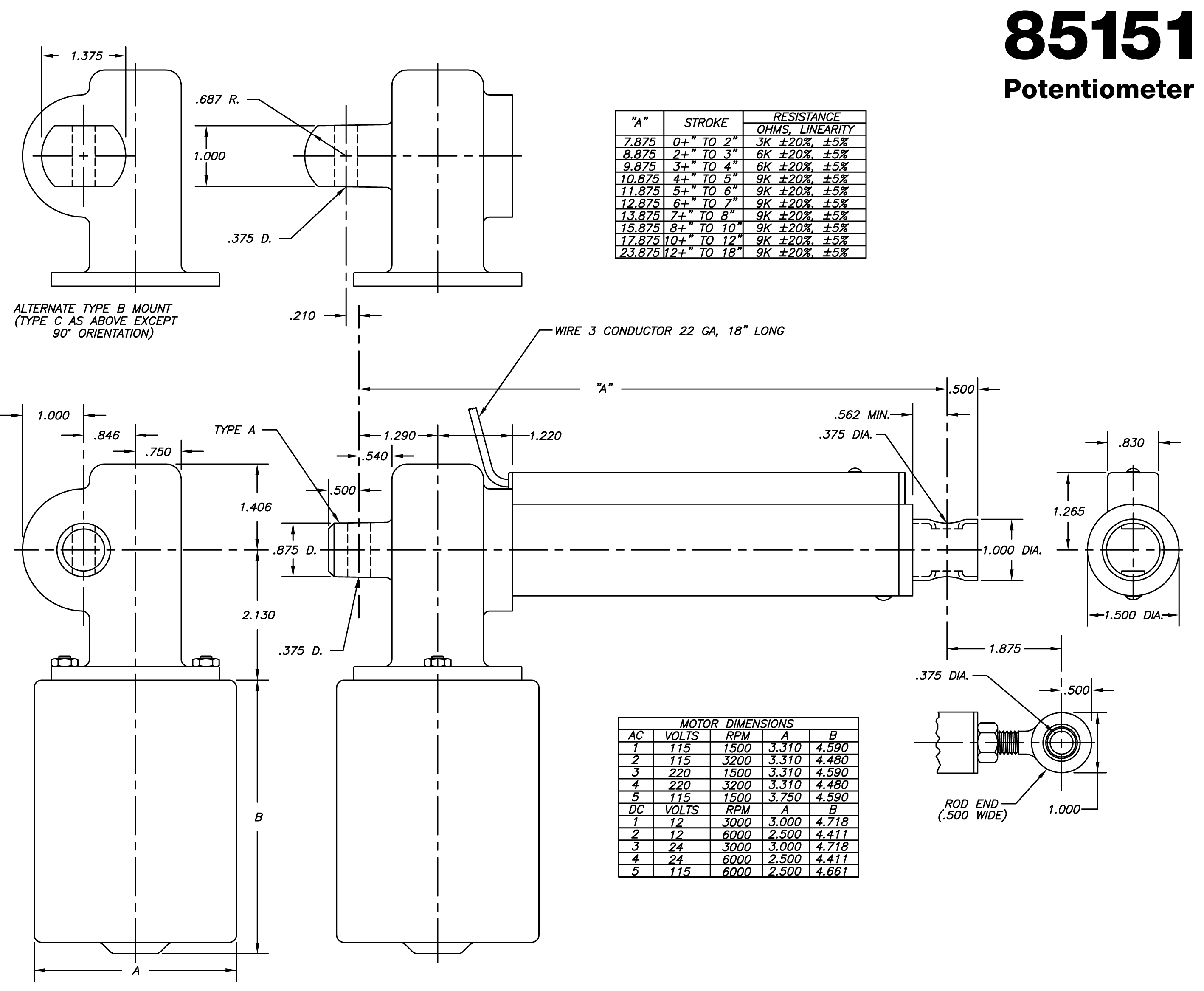
This is accompanied by enclosing a linear potentiometer in a special cover tube on the actuator. The potentiometer is an infinitely variable membrane type device. An excitation voltage is applied to it and read by a voltage sensing circuit such as a voltmeter. A wiper is attached to the ball nut and translates along the length of the potentiometer. As the wiper moves, the voltage received by a voltmeter varies accordingly.
The potentiometer has three leads. An excitation DC voltage is applied to the red lead. The black lead is the ground at 0 VDC. The white lead gives an output DC voltage signal that varies linearly with the position of the actuator.
It is usually simplest to select an excitation DC voltage that is an even multiple or divider of the actuator’s stroke. For example, if the actuator in the application has a 6 inch stroke, select an excitation voltage of say 6 or 12 volts. This allows easy scaling of the voltage. The actuator motor and the potentiometer power should be completely independent from each other to avoid noise problems.
The power rating for the potentiometer is 1 watt maximum. Mechanically, the device is capable of 1 million cycles and will operate over a temperature range of -45°C to 75°C.
The linear potentiometer is provided only as a method of measuring the actuator’s position. It is left to the user to provide a method of reading the signal, interpreting the signal and devising a control scheme for the particular application.
Ball Screw
The 85151 Actuator transmits thrust with the Epicyclic Ball Screw. This device has a unique freewheeling feature to prevent over travel at the end of stroke. A ball cage within the nut ID cams up against stop pins at each end of travel to initiate freewheeling and linear advancement stops. The stop pins are mounted in the screw thread and are factory installed for the specified stroke. This design generally eliminates the need for externally mounted limit switches. The Ball Screw diameter of .653 with an advancement per revolution of .187. All elements: screw, nut and ball cage are heat treated alloy steal with bearing surfaces for long wear characteristics. The nut is provided with a 15/16 thread for attachment of the translating tube on the 85151. Efficiency of the Ball Screw is 90%.
Gear Reducer
Motor speed reduction to drive the Ball Screw is by a single stage worm gear reducer. The housing is die cast aluminum alloy. A molded neoprene coupling with steel inserts couples the motor shaft to the worm shaft and provides protection against shock loads. The worm shaft runs in an oilite bearing at the motor end and a ball bearing at the opposite end. The Ball Drive is mounted in a ball bearing at the output side of the gear reducer which takes axial thrust loads, and an oilite bearing at the opposite end. Both the worm and gear are heat treated steel for long wear life. The ratios are: 10:1, 20:1 and 40:1. The gear reducer is sealed and permanently lubricated with a high grade synthetic grease. Special lubricants are available for extreme applications such as low temperature.
Motors
115 VAC, 220 VAC, 12 VDC, 24 VDC and 115 VDC motors are all stock units. The AC motors are permanent split capacitor induction type and are specifically designed for high starting torque with an intermittent duty cycle (25%). Either a 1500 or 3200 RPM speed may be selected and a 1500 RPM continuous duty version is also available. DC motors are permanent magnet brush type. An intermittent duty cycle (60%) is required on DC units. No load speeds are 6000 RPM and 3000 RPM. Motors with other voltages and performance characteristics are available on request.
Stroke
Any stroke length may be specified up to 72".
Available in inches or millimeters, with no limitation on interim dimensions.
Design Options 85151/85152
Gearbox Mounting
Normally the Type A gearbox mount with a .375 diameter crosshole oriented parallel to the motor shaft is provided; however a 90˚ orientation or any other angle can be specified to facilitate mounting and clearances in customer equipment. Other diameter crossholes can be provided such as .250 or .312. Alternately, the Type B or Type C mount can be provided and these permit the use of a larger mounting hole such as .437 or .500.
Brakes
A bi-directional friction brake which provides load holding and antidrift is normally specified with the 20:1 and 10:1 gear ratios. Many linkage type applications have balanced loads where a brake is not necessary. While the 40:1 ratio is self –locking.
Design Options 85151
Cover Tubes
An aluminum cover tube with a quad ring seal at its outboard end is available for applications which require protection of the screw.
Rod End
A self-aligning rod end is available for the outboard end of the translating tube. It provides fine adjustment (± .125) of the centerline mounting dimension of the actuator to compensate for tolerance buildup in customer assemblies. Minimum retracted and extended centerline mounting dimensions are increased by 1.875 with this option.
Supporting Bushing
For applications with compressive loads, particularly where the stroke is 6.000 or longer, it is recommended that a support bushing be included. This bushing is mounted on the end of the screw and rides within the translating tube to assist alignment throughout the stroke. For strokes of 12.000 or longer, a support bushing is generally recommended whether loads are tension or compression. The actuator minimum retracted and extended centerline mounting dimensions are increased by 1.250 with this feature.
Weatherproof Motor Enclosure
Where normal operating conditions are severe, a weatherproof motor enclosure is available for the AC motors. This housing has an outside diameter of 4.000 and increases the B dimension to 6.500 for all AC units. DC motors are adequately sealed so that additional enclosure is not required.
Technical Data Ball Drive Actuator 85151/85152 |
||||||||||||||
|
LOAD CAPACITY |
500 lbs. (dynamic) 3000 lbs. (static) Note: 500 lb. load rating can be extended in certain applications. |
|||||||||||||
|
|
||||||||||||||
|
STROKE |
2, 3, 4, 5, 6, 7, 8, 10, 12, 18, and 24 are only strokes available. | |||||||||||||
|
|
||||||||||||||
|
STROKE SPEED |
AC Motors: Gear Ratio 115, 220 VAC 1500 RPM 115, 220 VAC 3200 RPM |
|
||||||||||||
|
|
||||||||||||||
|
DC Motors: Gear Ratio 12, 24 VDC (PM) 3000 RPM 12, 24 VDC (PM) 6000 RPM 115 VDC (PM) 6000 RPM Note: Stroke speeds are in./sec with no load speed shown first and 500 lb. load speed shown second. |
|
|||||||||||||
|
|
||||||||||||||
|
GEAR |
10:1, 20:1, 40:1 | |||||||||||||
|
|
||||||||||||||
|
MOTORS |
AC Motors: 1) 115 VAC 60/50 Hz., Permanent Split Capacitor Induction, 3.3 diameter, 1500 RPM, intermittent duty cycle (25%), 3 wire, enclosed construction, automatic reset thermal overload protector, UL, CSA recognized, 1.6 amps no load, 1.7 amps at 500 lbs. with 20:1 ratio, 18 MFD electrolytic capacitor supplied. 2) 115 VAC 60/50 Hz., Permanent Split Capacitor Induction, 3.3 diameter, 3200 RPM, intermittent duty cycle (25%), 3 wire, enclosed construction, automatic reset thermal overload protector, UL, CSA recognized, 1.2 amps no load, 1.7 amps at 500 lbs. with 20:1 ratio, 18 MFD electrolytic capacitor supplied. |
3) 220 VAC 60/50 Hz., Permanent Split Capacitor Induction, 3.3 diameter, 1500 RPM, intermittent duty cycle (25%), 3 wire, enclosed construction, automatic reset thermal overload protector, UL, CSA recognized, 1.0 amps no load, 1.1 amps at 500 lbs. with 20:1 ratio, 6 MFD oil filled capacitor supplied. 4) 220 VAC 60/50 Hz., Permanent Split Capacitor Induction, 3.3 diameter, 3200 RPM, intermittent duty cycle (25%), 3 wire, enclosed construction, automatic rest thermal overload protector, UL, CSA recognized, .8 amps no load, 1.1 amps at 500 lbs. with 20:1 ratio, 6 MFD oil filled capacitor supplied. 5) 115 VAC 60/50 Hz., Permanent Split Capacitor Induction, 3.8 diameter, 1500 RPM, continuous duty, 3 wire, enclosed construction, automatic reset thermal overload protector, UL, CSA recognized, .6 amps no load, .8 amps at 500 lbs. with 20:1 ratio, 10 MFD oil filled capacitor supplied. |
||||||||||||
|
|
||||||||||||||
|
MOTORS |
DC Motors: 1) 12 VDC Permanent Magnet Brush, 3.0 diameter, 3000 RPM (no load), intermittent duty cycle (60%), 2 wire, enclosed construction, 2 amps no load, 10 amps at 500 lbs. with 20:1 ratio. 2) 12 VDC Permanent Magnet Brush, 2.5 diameter, 6000 RPM (no load), intermittent duty cycle (60%), 2 wire, enclosed construction, 6 amps no load, 15 amps at 500 lbs. with 20:1 ratio. 3) 24 VDC Permanent Magnet Brush, 3.0 diameter, 3000 RPM (no load), intermittent duty cycle (60%), 2 wire, enclosed construction, 1 amp no load, 5 amps at 500 lbs. with 20:1 ratio. |
4) 24 VDC Permanent Magnet Brush, 2.5 diameter, 6000 RPM (no load), intermittent duty cycle (60%), 2 wire, enclosed construction, 3 amps no load, 8 amps at 500 lbs. with 20:1 ratio. 5) 115 VDC Permanent Magnet Brush, 2.5 diameter, 6000 RPM (no load on rectified 115 VAC), intermittent duty cycle (60%), 2 wire, enclosed construction, 1.1 amps no load, 2.1 amps at 500 lbs. with 20:1 ratio. |
||||||||||||
|
|
||||||||||||||
|
BALL DRIVE |
Epicyclic Ball Screw with integral freewheeling at ends of stroke. Screw OD: .653 Screw root dia.: .562 Advancement/rev.: .187 Centerline pin dimension: 1.562 + stroke Nut OD: 1.000 |
Nut mounting: 15/16-16 thread. Materials: heat-treated alloy steel with bearing races. Efficiency: 90% |
||||||||||||
|
|
||||||||||||||
|
GEAR REDUCER |
Single stage worn gear type with 6302 ball bearing to accommodate ball screw thrust. Housing: die cast aluminum alloy. Bearings: worm shaft and Ball Drive shaft both supported on sleeve bearing and ball bearing. |
Worm and gear materials: heat treated steel. Motor coupling: 70 durometer neoprene with two heat treated steel inserts. Lubrication: permanently lubricated with synthetic grease. Special lubricants are available for extreme applications such as low temperature. |
||||||||||||
|
|
||||||||||||||
|
WEIGHT |
85151: 6.9 lbs. (6 in. stroke with AC motor) 6.2 lbs. (6 in. stroke with DC motor – 3.0 dia. PM) | 85152: 6.5 lbs. (6 in. stroke with AC motor) 5.8 lbs. (6 in. stroke with DC motor – 3.0 dia. PM) | ||||||||||||