Feedback Linear Actuator 85615 Potentiometer
The Motion 85615 Linear Actuator provides a miniature package for operating loads up to 100 lbs.
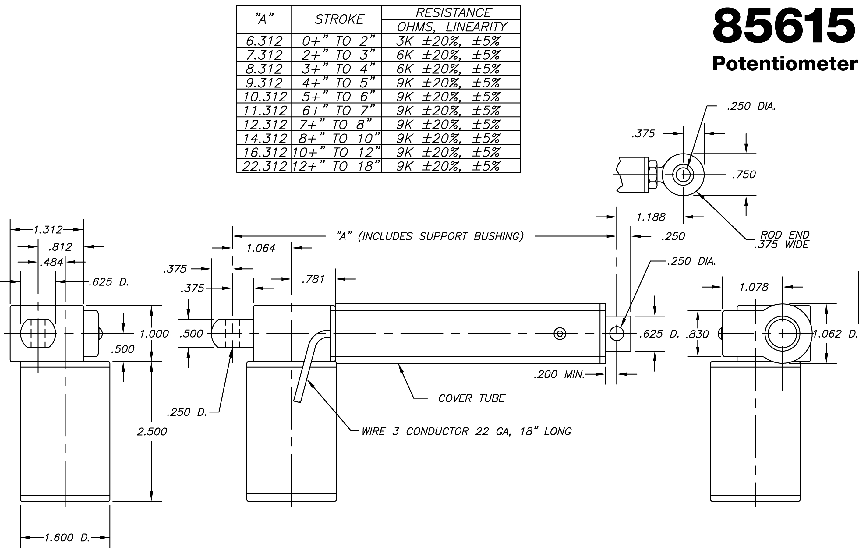
In some applications it is necessary to provide a simple and reliable way to measure the actuator’s position.
| Potentiometer Wiring | MOTOR Wiring |
This is accomplished by enclosing a linear potentiometer in a special cover tube on the actuator. The potentiometer is an infinitely variable membrane type device. An excitation voltage is applied to it and read by a voltage sensing circuit such as a voltmeter. A wiper is attached to the ball nut and translates along the length of the potentiometer. As the wiper moves, the voltage received by a voltmeter varies accordingly. The potentiometer has three leads. An excitation DC voltage is applied to the red lead. The black lead is the ground at 0 VDC. The white lead gives an output DC voltage signal that varies linearly with the position of the actuator.
It is usually simplest to select an excitation DC voltage that is an even multiple or divider of the actuator’s stroke. For example, if the actuator in the application has a 6 inch stroke, select an excitation voltage of say 6 or 12 volts. This allows easy scaling of the voltage. The actuator motor and the potentiometer power should be completely independent from each other to avoid noise problems.
The power rating for the potentiometer is 1 watt maximum. Mechanically, the device is capable of 1 million cycles and will operate over a temperature range of -45°C to 75°C.
The linear potentiometer is provided only as a method of measuring the actuator’s position. It is left to the user to provide a method of reading the signal, interpreting the signal and devising a control scheme for the particular application.
Technical Data Linear Actuator 85615/85616 |
||||||||
|
LOAD CAPACITY |
100 lbs. (dynamic) 600 lbs. (static) Note: 100 lb. load rating can be extended in certain applications. |
|||||||
|
|
||||||||
|
STROKE |
2, 3, 4, 5, 6, 7, 8, 9, 10, 12 and 18 inches are the only strokes available. | |||||||
|
|
||||||||
|
STROKE FEED |
DC Motors: Gear Ratio 12,24 VDC (PM) 7500RPM Note: Stroke speeds are in./sec with no load speed shown first and 100 lb. load speed shown second. |
|
||||||
|
|
||||||||
|
GEAR |
7.5:1, 15:1, 30:1 | |||||||
|
|
||||||||
|
MOTORS |
DC Motors: 1) 12 VDC Permanent Magnet Brush, 1.6 diameter, 7500 RPM (no load), intermittent duty cycle (60%), 2 wire, enclosed construction, .4 amps no load, 3.4 amps at 100 lbs. with 15:1 ratio. |
2) 24 VDC Permanent Magnet Brush, 1.6 diameter, 7500 RPM (no load), intermittent duty cycle (60%), 2 wire, enclosed construction, 2 amps no load, 1.7 amps at 100 lbs. with 15:1 ratio. |
||||||
|
|
||||||||
|
BALL |
Epicyclic Ball Screw with integral freewheeling at ends of stroke. Screw OD: .331 Screw root dia.: .280 Advancement/rev.: .125 Centerline pin dimension: .957 + stroke Nut OD: .625 |
Nut mounting: 9/16-18 thread. Materials: heat-treated alloy steel with bearing races Rockwell 56C. Efficiency: 90% |
||||||
|
|
||||||||
|
GEAR REDUCER |
Single stage worn gear type with 626 ball bearing to accommodate ball screw thrust. Housing: die cast aluminum alloy. Bearings: Ball Drive shaft supported on sleeve bearing and ball bearing. |
Worm and gear materials: heat treated steel. Lubrication: permanently lubricated with synthetic grease. |
||||||
|
|
||||||||
|
WEIGHT |
85615: 1.3 lbs. (6 in. stroke) | 85616: 1.0 lbs. (6 in. stroke) | ||||||